Computer From Scratch
Posted on July 19, 2015 by
Recently I have had the pleasure of completing the course Nand to Tetris on Coursea. Firstly, I'd like to highly recommend it to anyone! I never thought it would be possible for me to understand computers all the way down to the hardware level (past assembly that is); Nand to Tetris has shown me otherwise! It has also inspired me to pursue learning a real world hardware description language and attempt to implement the Hack system on an FPGA (Field Programmable Gate Array). In this article I will describe how the process is coming and the what remains to be completed.
For the impatient, the repository is located here and is documented here.
After implementing the Hack Computer System in the hardware description language described by the course, I wanted to explorer further. So after doing a little research, I found there were two main industry strength hardware description languages, VHDL and Verilog. I then set out to find open source implementations of these languages. Happily I found GHDL and Icarus Verilog respectively. After briefly looking over both languages and their open source implementations, I decided I would use VHDL because I'm a fan of type systems and it is similar to the hardware description language given by the Nand to Tetris course.
Now both Icarus Verilog and GHDL are unable to do synthesis. For those of you who are unaware of what synthesis is, it refers to the process of taking a hardware description and converting it into a format a FPGA can use. This is generally a bit file for JTAG programming or a bin file for writing to the FPGA board's internal memory. To my dismay, FPGA's are incredibly proprietary! Namely, the synthesis process can only be done using proprietary tools. So initially I decided I would forgo thinking about how exactly I would get my implementation on a FPGA but instead get the components of the system designed and verified though simulation, which can be completed using all open source tools. Now, there is a unsynthesizable subset of both VHDL and Verilog, so care needs to be taken to ensure that the design doesn't utilize these parts as the end goal is to implement the Hack Computer System on a FPGA. An exception to this is when a entity/module will only be used in simulation (Eg. Reading a text file and emulating a ROM that contains the machine language instructions specified in the file).
Following the materials given by the course, I then went on to implement the Hack Computer System in VHDL. Currently, the project resides here and has some accompanying documentation which explain how things work, how to build the project, and how to run a simulation. Please refer to the documentation for complete instructions on building and using the hack project and simulator.
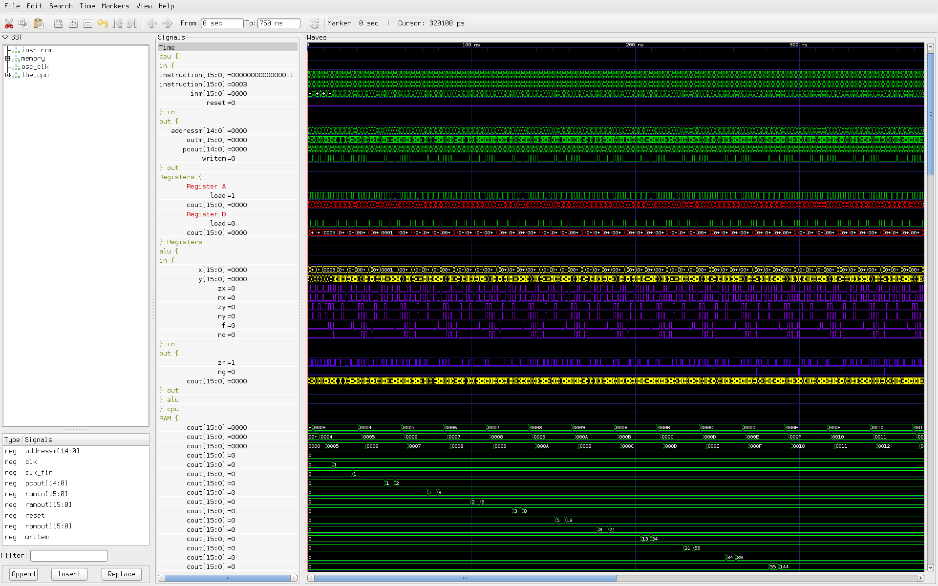
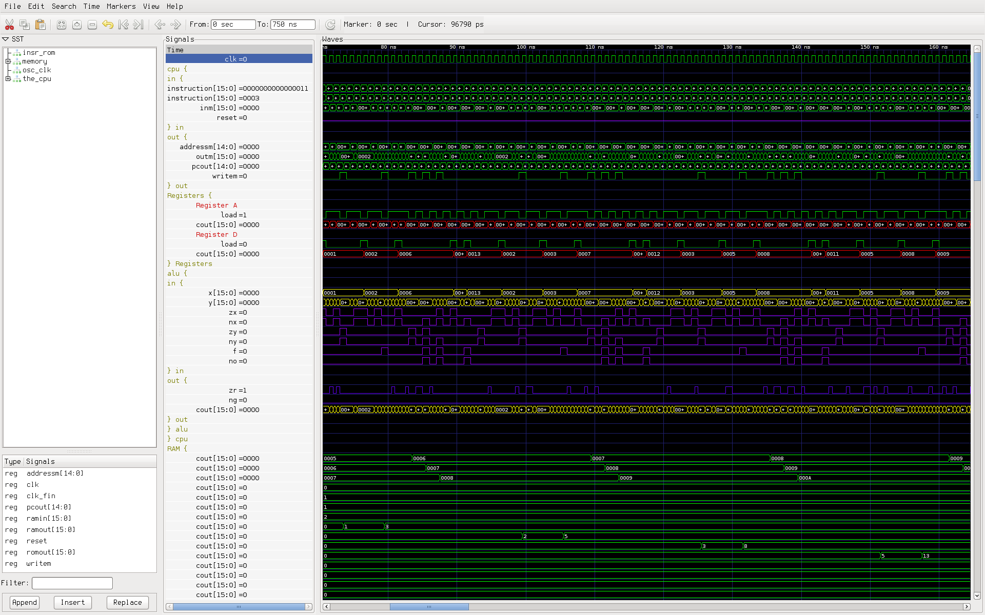
Before going into detail on some of the design choices I made, I'd like to give an example of
setting up the simulator and running the default simulation of the top most unit,
computer_tb, which computes the first 25 Fibonacci numbers and puts them in RAM address' 0x3
through 0x28.
$ git clone http://git.rekahsoft.ca/hack
$ cd hack/src
$ ghdl -i --workdir=work *.vhdl
$ ghdl -m --workdir=work computer_tb.vhdl
$ ghdl -r computer_tb --stop-time=750ns --vcd=wave/vcd/computer-fib.vcd
$ vcd2fst wave/vcd/computer-fib.vcd wave/vcd/computer-fib.fst
First, clone the sources, then import and build them with ghdl. Finally run the simulation
using the default input program and output a vcd file to src/wave/vcd/computer-fib.vcd which
is then converted to a fst file using vcd2fst (vcd2fst is included with GtkWave). Now
once the simulation has complete the vcd or fst file can be opened with a wave form viewer.
I recommend and have only tested with GtkWave. To open the dump file open GtkWave and
go to File -> Open New Tab (or C-t) and select the output file (in our case
src/wave/vcd/computer-fib.fst). I have provided pre-saved "views" for computer_tb (as well
as the other entities within the project) so that the signals of interest for the entity in
question don't need to be repopulated into the signals panel each time GtkWave is opened.
To open the GtkWave save file go to File -> Read Save File (or C-o) and select the
appropriate save file. In our case we will open src/wave/gtkw/computer-fib.gtkw.
Note running this simulation will take some time (likely longer then an hour) and will consume lots of RAM and CPU and generate a large vcd dump (> 20 GB). By changing the length of time the simulation runs for one can limit the size of the vcd dump, but the usage of the CPU and RAM will remain the same. The large vcd dump file is unavoidable because GHDL records data for all signals in the design and there's no way to filter its output until after the simulation has run (using external tools). Hopefully at some point the developers of GHDL can fix this oversight.
Using a
generic property
program_file, a user is able to pass a text file containing Hack Machine Language to the
computer_tb unit using the -g switch to GHDL like so:
-gprogram_file=path/to/program.hack. If none is specified it defaults to
src/asm/Fib.hack (the corresponding Hack
assembly form is provided here). The
contents of the given program_file are used as the ROM data for the duration of the
simulation.
Unfortunately specifying generic properties when ghdl is invoked is only implemented in very
recent versions of GHDL (later then 2015-03-07; see
ticket). If you are running an
older version of GHDL then you must modify src/computer_tb.vhdl to specify the program you
want to run in the simulation. See the documentation for details.
So now that we've seen a quick rundown of how to use the simulator to run Hack programs, lets take a moment to review some of the deficiencies of the implementation. The most noticeable issue is that the memory maps for the SCREEN and KEYBOARD are currently not implemented. This is mainly because it is difficult to simulate keyboard input and video output in real time. Note that programs that access the SCREEN and KEYBOARD memory maps will successfully be executed during simulation, but any data sent to the screen will never be remembered and the keyboard will always be inactive.
One method to implemented the KEYBOARD memory map is using a text file similar to the technique employed in the ROM entity. This would work fine but wouldn't provide an interactive user experience as I would prefer. Similarly for video output, the raw VGA signals or even simpler yet, the values of the screen memory map could be dumped to file during the simulation and then be processed after the fact by an external program to create a video or set of images of the output. This again however, isn't a interactive experience.
An option I haven't mentioned is to have the simulation and an external program communicate through a pipe or socket while the simulation is running. This would allow the external program to send key presses to the simulation while also simultaneously decoding the output of the screen output file in real time and displaying it as a video to the user; essentially creating a VM for the Hack machine. This approach seems the most promising but is quite challenging to implement, and likely will be quite slow. So I determined for the time being, my time would be better spent focusing on completing the implementing on a FPGA, once I'm able to obtain one. Though at some point I may explore this as it would allow an easy way for students to further explore after completing the Nand to Tetris course.
Anyways, hope you enjoyed reading this post. I will post a few follow up articles once I'm able to obtain a FPGA and complete the implementation (will a VGA screen and a PS2 or USB keyboard). Also just to reintegrate, for those of those interested in the inner workings of a computer, I highly recommend checking out the Nand to Tetris course.